In This Section
Setting Connection Style by Pick
Basic Connection Style Settings
Connection Width
Setting the Connection Layer
Picking the Connection Layer
Connection Arrowheads
Displaying Connection Length and Attributes
Editing Connection Attribute Values
Setting Connection Style
The connection style settings apply to all new connections and lines or polylines converted to connections using the IQ tool.
The Apply Style (UPDATEPICK) tool applies all the style settings to an existing connection. Also see Editing Connections.
Setting Connection Style by Pick
Creating a connection by selecting an existing connection using the PICKVIS (Pick to Insert) tool sets the connection layer and style per the selected connection.
Basic Connection Style Settings
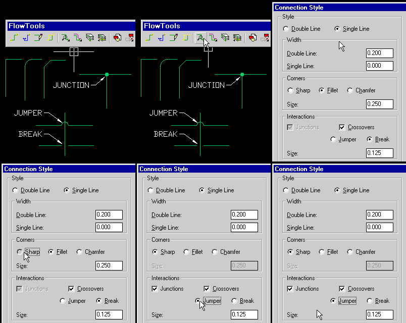
These setting affect basic connection appearance. The numerical values are multiplied by the Overall Scale value when connections are created.
Connection Width
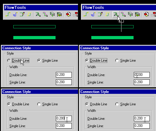
Two types of connection width are available, double line and single line. The single line width is per AutoCAD's polyline width parameter, whereas the double line width is unique to FlowTools.
Double lines will trim underlying connections and make superior wire and pipe representations.
Setting the Connection Layer
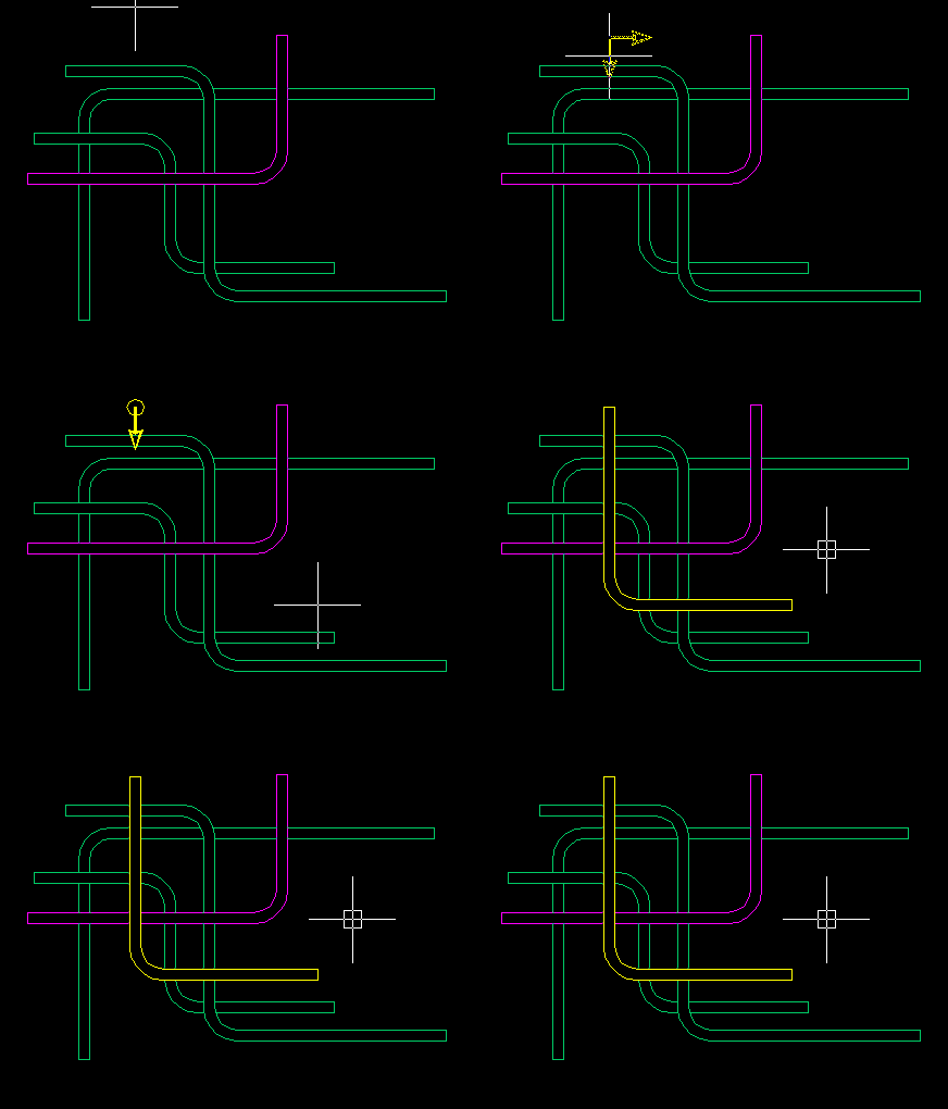
The connection layer can be set either via the DDLAYERS dialog or by picking any entity on screen already on the desired layer using the PICKCON tool.
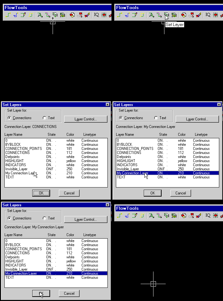
Picking the Connection Layer
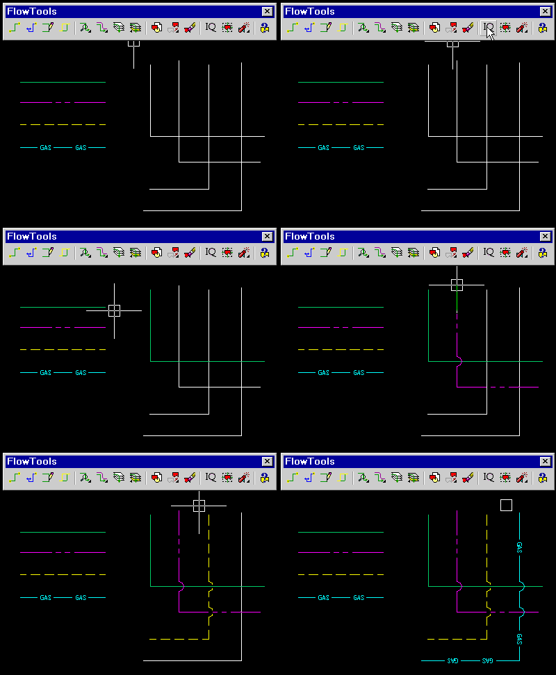
In this example, polylines are being converted to connections using the IQ tool with Convert To Layer set to Connection in the Options... dialog.
Connections appear in the color and linetype of their parent layer. The Apply Style tool can change the layer of an existing connector. Also see Editing Connections.
Connection Arrowheads
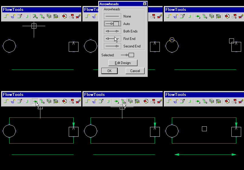
Arrowheads are set with the DDARROWS dialog.
When set to Auto an arrowhead is placed when a connection point is programmed for auto-arrow. See Editing Symbol Definitions. The white "V" in the rectangle shows a point programmed for auto-arrow.
Displaying Connection Length and Attributes
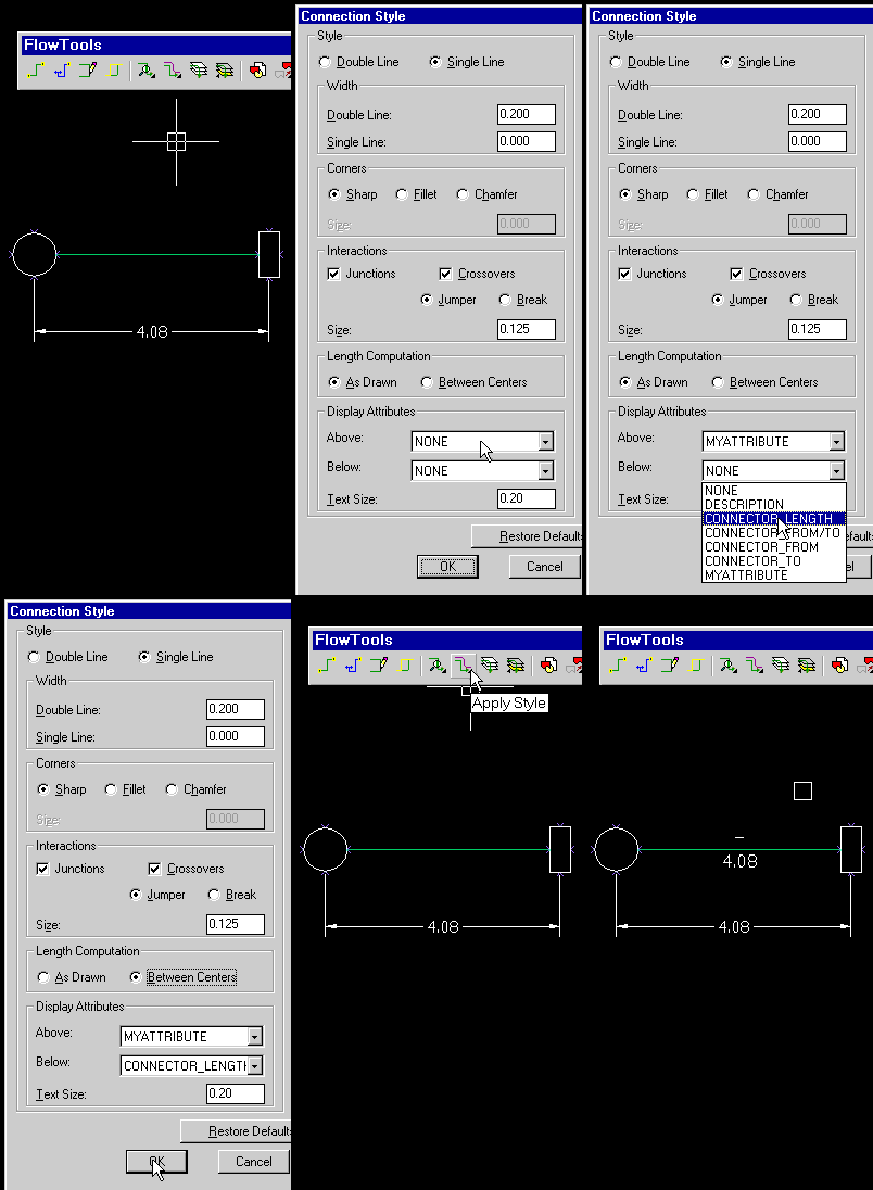
Two attributes can appear with a connection and will automatically stay attached to the connection if rerouted or edited. The text appears in the current AutoCAD style on the Text layer set in SETUPLEGEND.
In addition to the default length and from/to choices, the choices shown in the attribute popup lists are taken from the current columns set in SETUPLEGEND.
When computing connection length, you can choose to display the length of the connector as drawn on-screen, or the length between the origins of the symbols at either end, as shown in this example.
Editing Connection Attribute Values
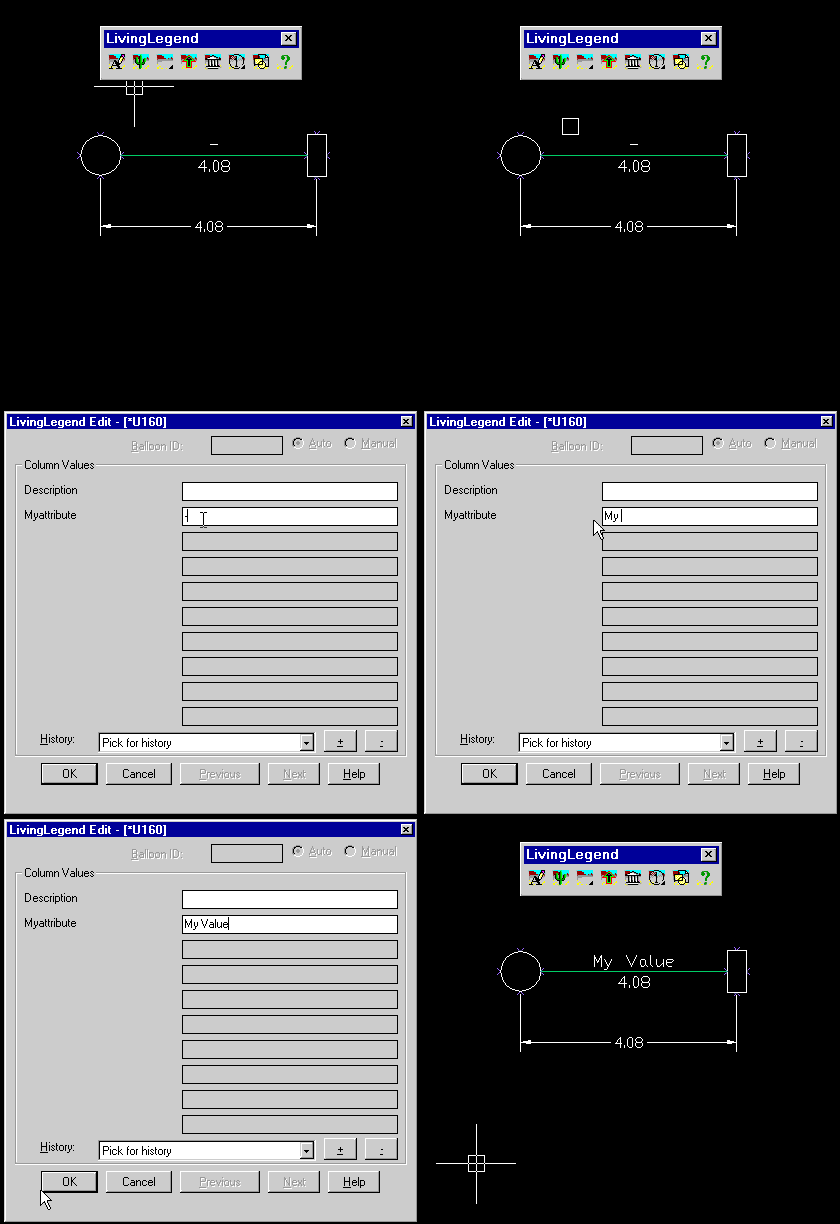
Use the EDITLEGEND tool to edit connection attribute values.
The attributes shown in the dialog are determined by the columns set using SETUPLEGEND.
