In This Section
Overall Scale
Options
Preferences
Units
Highlight Color
Displaying Connection Points
Save a Template
Drawing Setup
Overall Scale
The most important FlowTools drawing setup step is setting the “Overall Scale”. This setting effects the screen size of many connector and symbol parameters.
To set the Overall Scale, open the Connector Style dialog box and enter it into the upper right edit field.
A good starting number can be found by dividing the average size of the symbols you’ll be using by 2.0. So if your symbols are about 2” in width, enter an Overall Scale of 1.0, If your symbols are 24” wide, enter 12.0, etc. This is typically a “set-and-forget” setting for a drawing once you’ve got it working the way you want.

Options
The options dialog is used to change settings for inserting blocks and connectors. When converting lines/polylines to connectors, you can choose to create the connector on the current connector layer or on the polyline’s original layer.

Preferences
The preferences dialog determines the behaviors of FlowTools FSCALE and create text inside block commands. FlowTools can be set to scale blocks disproportionately and keep attributes the same size no matter how the block has been scaled.

Units
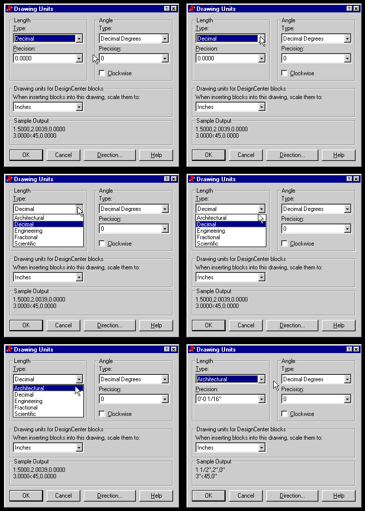
FlowTools and LivingLegend both use the current setting of AutoCAD’s UNITS command when displaying length values.

Highlight Color
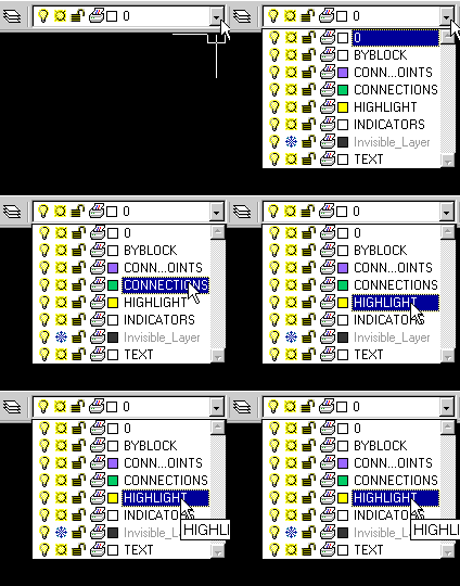
The special layer HIGHLIGHT determines the color of FlowTools’ highlighting, so if you work on a light background, you should set this color to dark blue or equivalent.


Displaying Connection Points
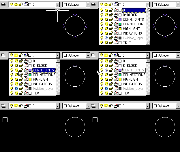
You can turn off the small, purple connection point locators by freezing special layer CONNECTION_POINTS using AutoCAD’s layer commands. You may likewise change their color on screen by changing the layer color.

Save a Template
Once you’ve established a working configuration of FlowTools drawing settings, use AutoCAD’s Save As command to save a template so that future new drawings will begin with those settings.