In This Section
Exploding a Symbol
Compiling a Symbol
Modifying Connection Points
Moving the Symbol Origin
Assigning Pin Names
Making an attribute visible
Boundary Indicators
Editing Symbol Definitions
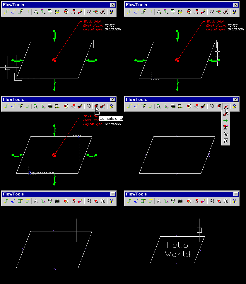
Exploding a Symbol
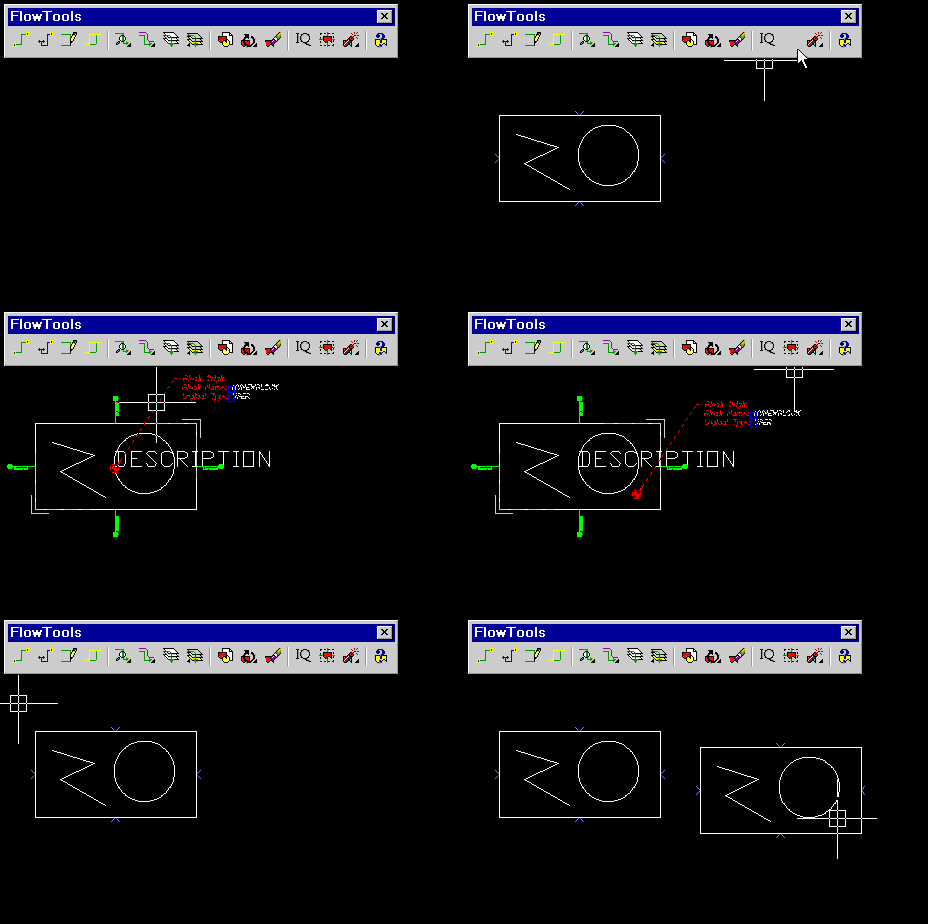
To edit a symbol definition, click on it with the FEXPLODE tool. You may do this in place on your drawing, even if the symbol has connectors attached to it.
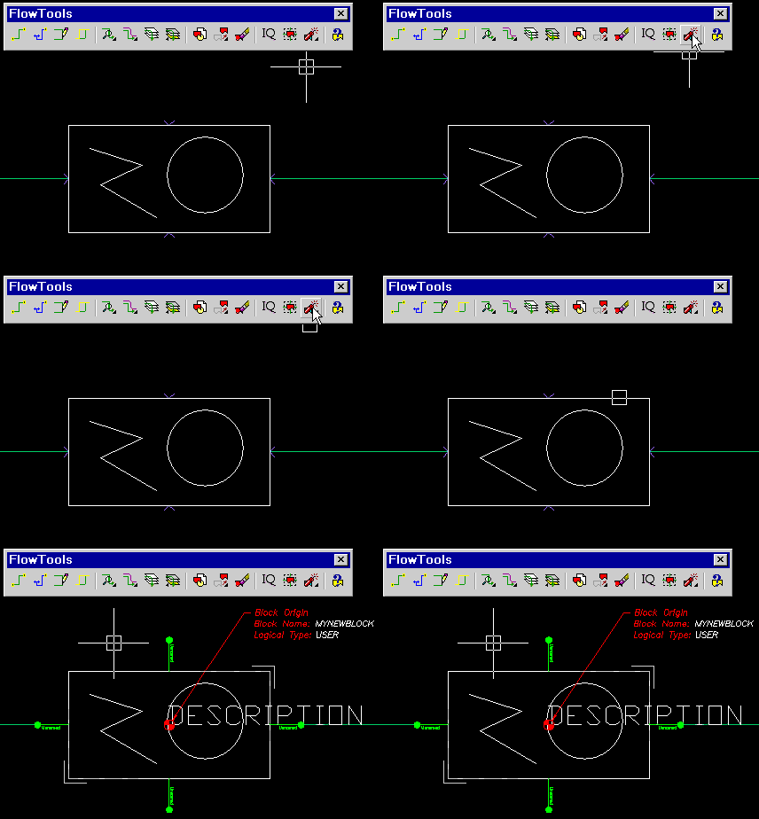
Compiling a Symbol
To compile a symbol, select all of the symbol entities and all of the symbol indicators that appeared when it was exploded. Any connectors selected will be ignored, so you can use a crossing window for your selection.
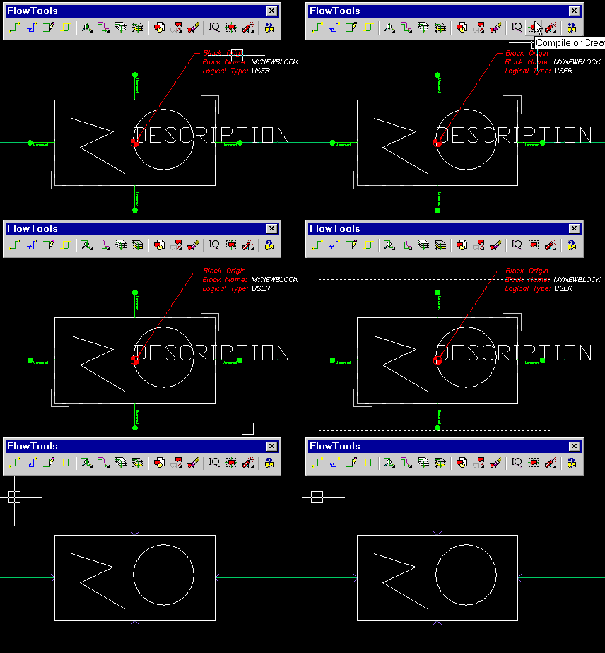
Modifying Connection Points
To add a new connection point, use the INSCON tool and specify the location and angle on screen. NOTE: connection point indicators must be orthogonal, i.e. vertical or horizontal. Non-orthogonal indicators are ignored.
To remove a connection point, erase its connection point indicator
Use FROTATE to change the angle.
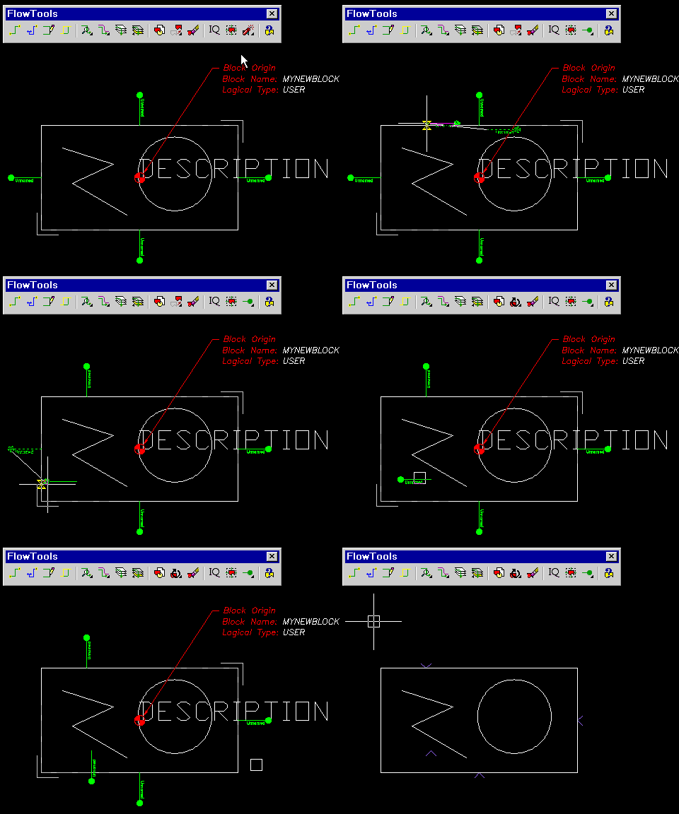
Moving the Symbol Origin
The red target determines the insert origin of a symbol. Use AutoCAD’s MOVE command to position it.
Assigning Pin Names
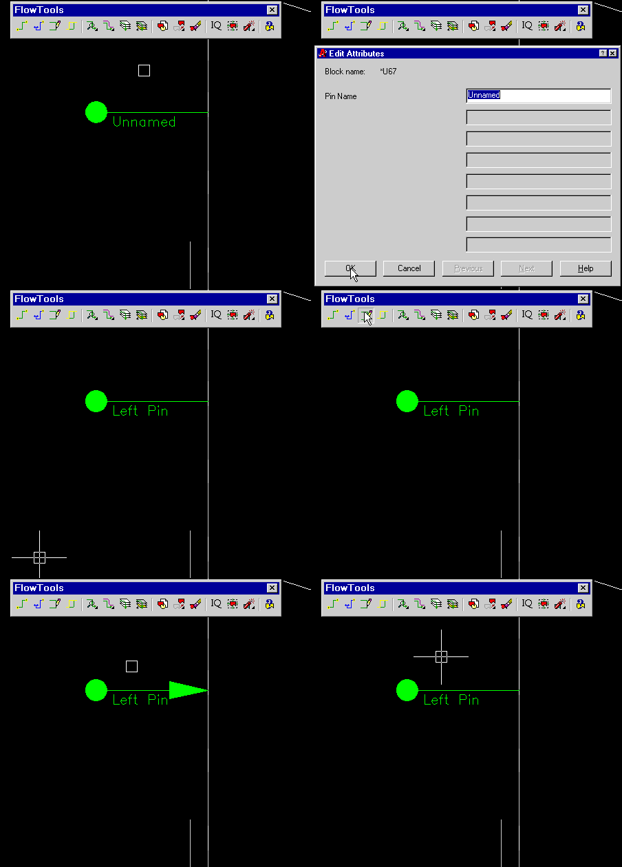
LivingLegend can automatically extract pin names and display connector from/to information. To assign a pin name, use AutoCAD’s DDATTE command and select a connection point indicator.
Pick a connection point indicator with the FEDIT tool to turn on connector auto-arrow. If arrowheads are set to "auto" an arrowhead will be placed at this point when a connector is attached.
Making an attribute visible
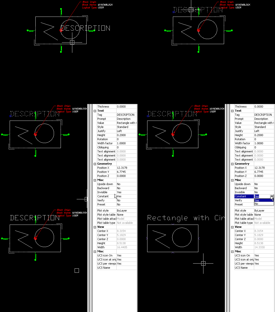
Select the attribute you wish to modify, then right-click on it and choose “Properties”. In the Misc. section of the Properties list, select “Invisible” and set it to “No”. You can optionally select “Constant” and set it to “No” if you want to make the attribute editable using DDATTE.
Also see the Text to Attribute tool.
NOTE: LivingLegend can edit the value whether or not it is constant, but constant attributes apply to all symbol instances on the drawing, whereas non-constant attributes can vary for each instance.
Boundary Indicators
The grey boundary indicators should enclose the visible parts of your symbol. They are used to determine automatic connector routes and the text field size for the Text Inside Block (TXTINBLK) command.
