In This Section
Setting up Legend Appearance
Preset Column Choices
Legend Options
Setting Legend Style by Pick
Setting Legend Appearance
Setting up Legend Appearance
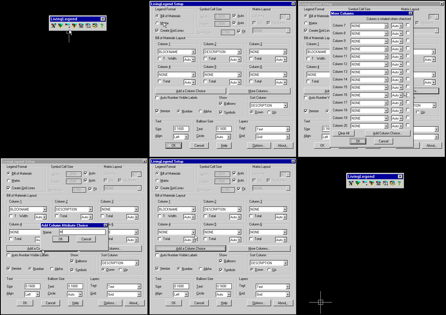
Use the SETUPLEGEND tool to open the Setup Legend dialog used to determine legend appearance. You may choose a Matrix or BOM format (See Creating Legends). Text and Grid lines can be placed on chosen layers, and the text size selected. Text style is per the current AutoCAD text style.
In BOM format, up to twenty columns can be used. To create a new column heading, use the Add a Column Choice button. This determines the attribute tag for new attributes created when legend data is entered.
To show a column total, check the "T" toggle. The "Width" setting can be automatically determined by the legend data, or you can set a character width.

Preset Column Choices
The preset column choices are reserved attribute names. Use CONNECTION_LENGTH to display connection length (See Connection Style), and the various FROM/TO choices to display the LABEL and pin name of the symbols to which a connection attaches.
Legend Options
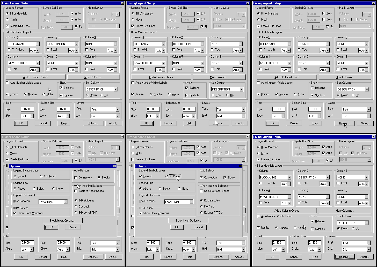
The Options... button accesses settings for auto-ballooning connections or blocks, determining the layer symbols are placed on in your legend and other various parameters.

Setting Legend Style by Pick
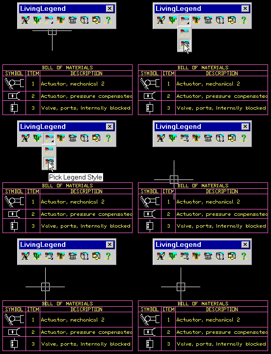
Use the LEGENDSTYLE tool to set legend appearance to any existing legend. You may pick a legend on a different drawing.
The next legend created will use the selected legend's appearance settings.
